TXW13 Hubs and Knuckles
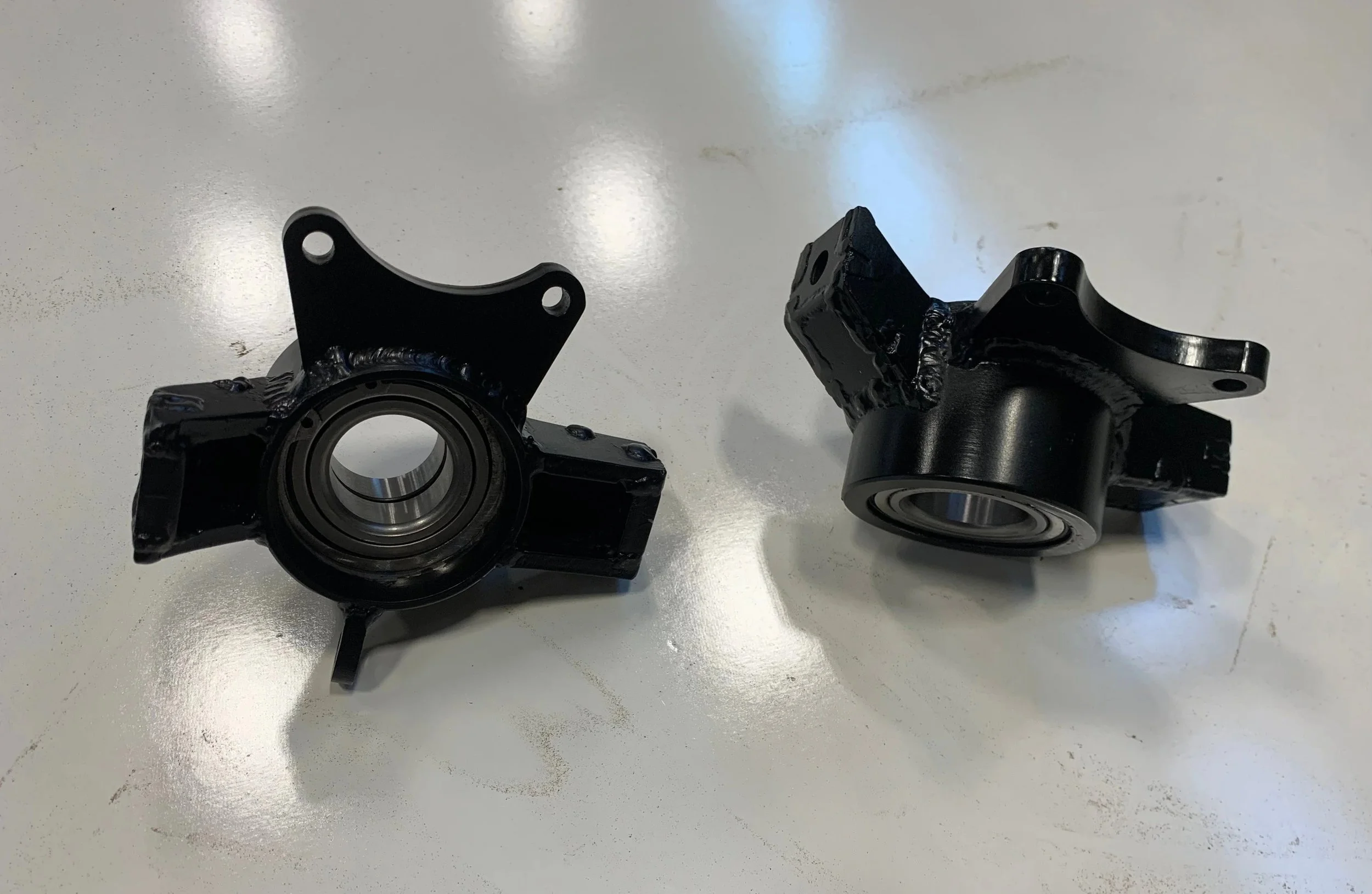
Front knuckles with caliper carriers and bearings pressed it.
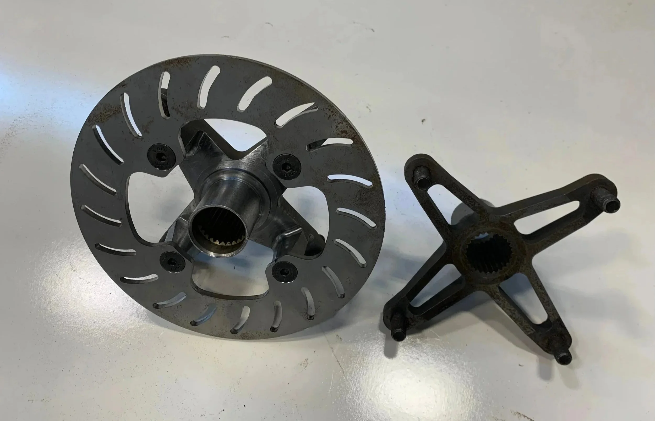
Front hub (left) with brake rotor bolted on and rear hub (right)
Knuckle Design
As part of the Baja SAE vehicle development, I led the design of the suspension knuckles, a critical component connecting the A-arms, hubs, and braking system while supporting all cornering and vertical loads. The design process involved three major iterations, each building on lessons learned from the previous version to achieve the optimal balance of strength, cost, manufacturability, and weight.
First Iteration
The first iteration(on the right) focused on packaging and geometry, ensuring proper alignment of the suspension pick-up points, wheel hub, and brake caliper within the space constraints of the chassis and wheels. While this version established the basic layout, it was found to be overbuilt and heavier than desired. This iteration was also based on CNC machining the knuckles out of aluminum.
Second Iteration
The second iteration addressed these issues by removing unnecessary material, changing the design to be made with one central bearing holder with tabs that could be welded onto for the suspension arms, which simplified design for manufacturing. Finite Element Analysis (FEA) was used to evaluate stress concentrations and deflection under simulated cornering and bump loads, which revealed that the suspension tabs were welded too far from their intended locations, creating poor load paths and weakening the overall structure. Although this version reduced weight and improved manufacturability, it still presented challenges in terms of camber and scrub radius and required complex jigging for fabrication.
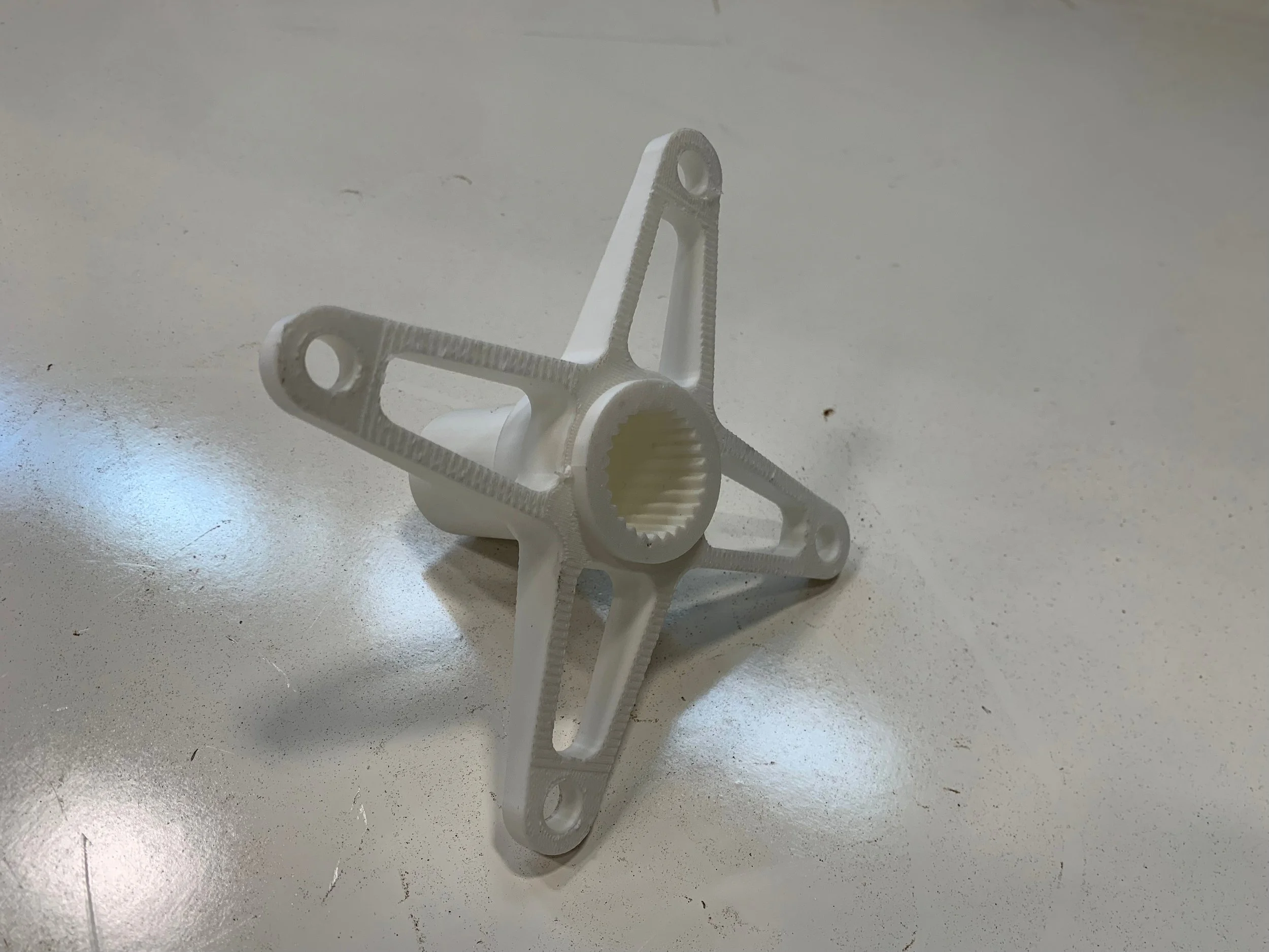
Third Iteration
The final iteration combined the geometric efficiency achieved in the second version with a form specifically optimized for fabrication. The shape was refined to allow the knuckle to be accurately positioned in a 3D-printed welding jig, which made it easier to locate and weld the suspension mounting tabs with consistent precision. The suspension mounting tabs were also designed so that there would not be a significant bending moment on them. This adjustment simplified the manufacturing process while preserving the structural integrity verified through FEA. The result was a lightweight, robust knuckle that met the team’s performance targets.

Knuckle Manufacturing
The manufacturing process began with machining a central steel component on a lathe, which serves as the main hub of the knuckle and houses the bearing that supports the wheel hub. Once complete, suspension mounting tabs were accurately positioned around the central piece using a 3D-printed welding jig to ensure consistent geometry. The tabs were then TIG-welded in place, creating a rigid assembly with precise suspension pickup point locations. This approach combined the accuracy of CNC machining with the flexibility of welded fabrication, resulting in a knuckle that is both durable and repeatable to produce.
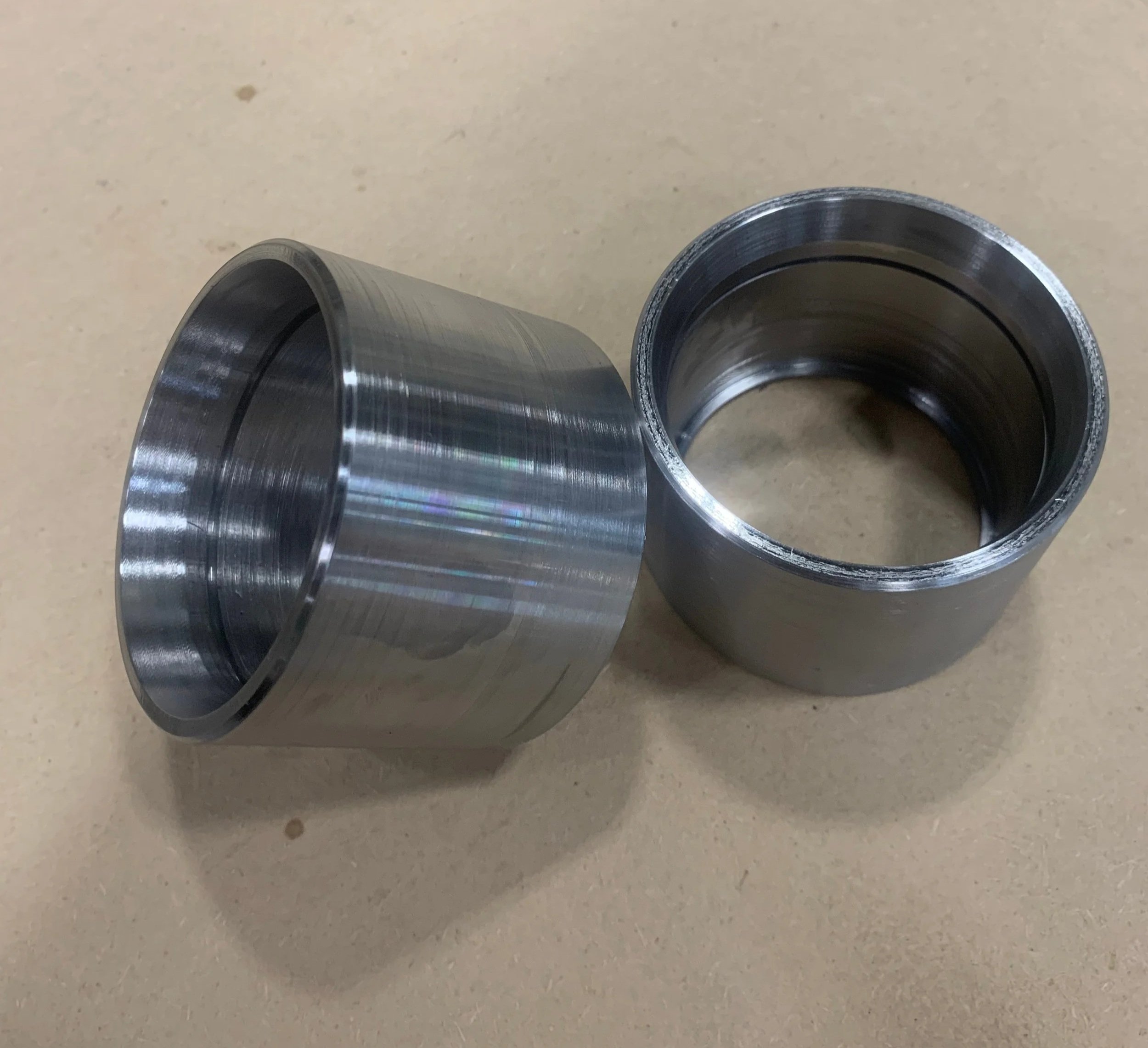
Hub Design
It was initially intended for the wheel hubs to fit snugly inside the suspension system, however it was discovered during the first mock-up that the brake calipers were interfering with the wheels' inner surface. This problem made it evident that the hub geometry needed to be changed to allow for adequate clearance while keeping the driving and braking components aligned. This was fixed by adding a small offset to the hub design, which moved the wheel mounting face outward just enough to get past the calipers without sacrificing suspension geometry.
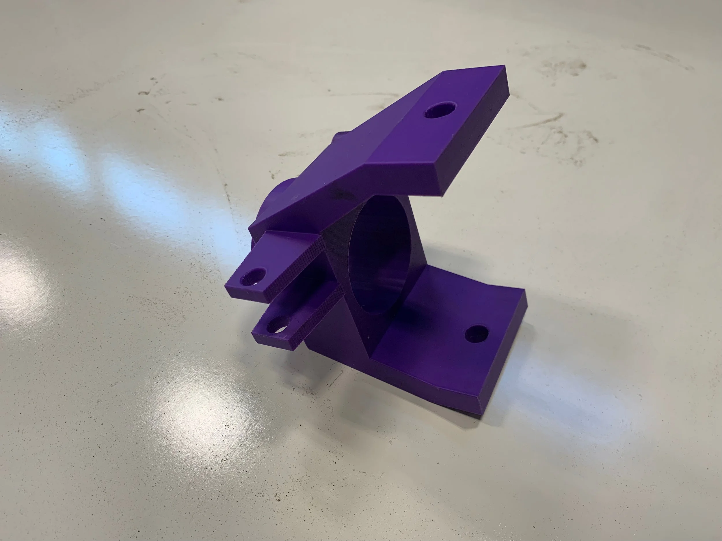
First iteration without wheel offset

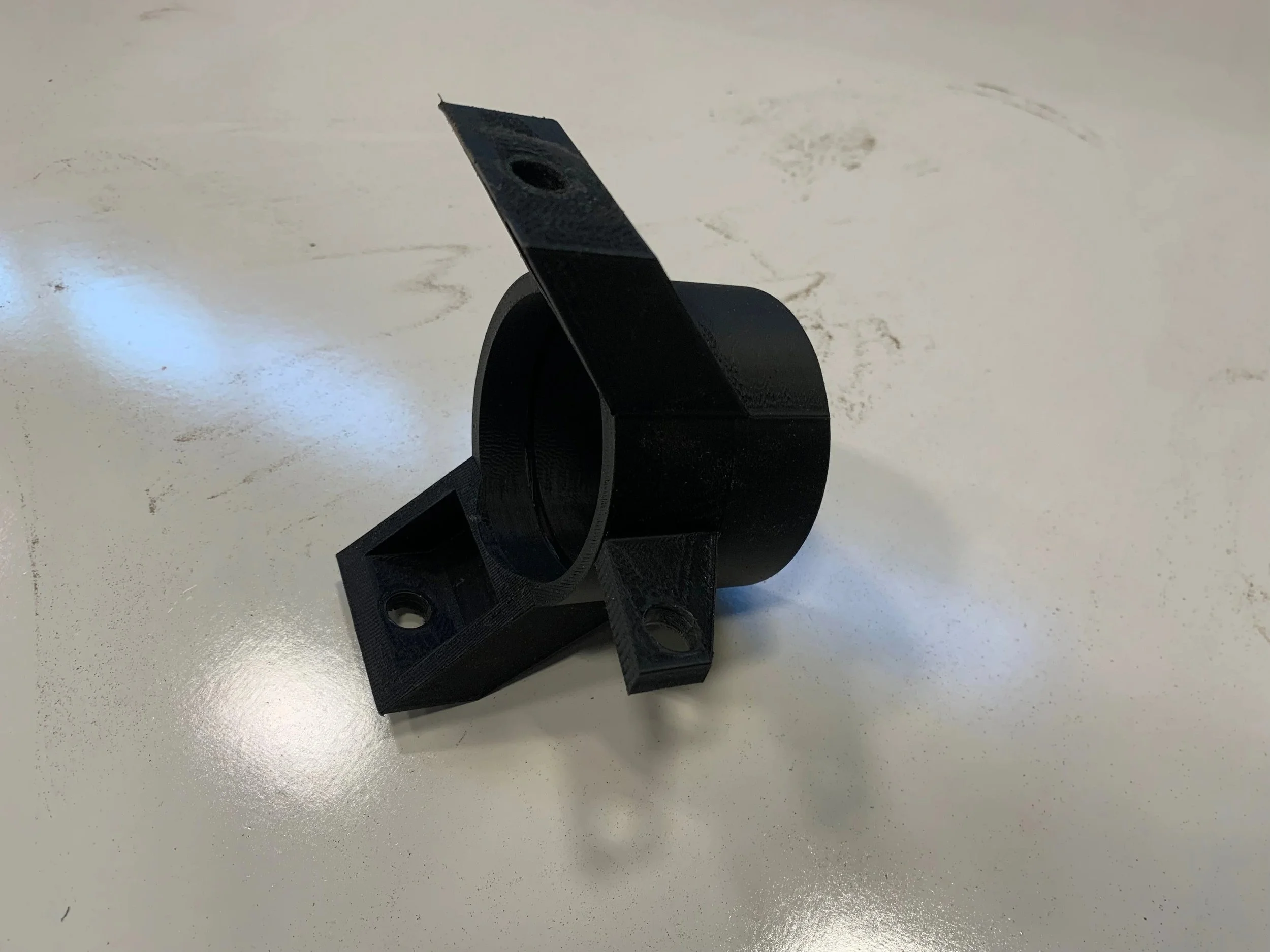
Final iteration with wheel offset